


Fluorine lined butterfly valve
Full-fluorine-lined butterfly valve — A216 WCB or CF8/CF8M body, PTFE/PFA/FEP lining on all wetted surfaces. DN50–DN1600, PN1.0/1.6/150LB. Split-body design with fluororubber + PFA encapsulated O-ring at the stem — zero leakage at the shaft even under thermal cycling. Lining options span –30°C to 200°C depending on polymer. Wafer, lug, or flanged connection. HG/T 3704, GB/T 12238, API 608. For acids, alkalis, solvents, and oxidizing media where the valve body must never see bare metal in the flow path.
- Nominal Diameter: DN40 – DN1600
- Pressure Rating : 1.0 MPa / 1.6 MPa / 150LB
- Body Material: A216 WCB · A351 CF8 · CF8M · CF3 · CF3M
- Lining Material:PTFE (–30~180°C) · PFA (–30~200°C) · FEP (–30~150°C) · RPTFE · GXPO
- Connection Type : Wafer · Flanged RF
- Shell Test Pressure (Water) : 1.5 MPa
- Design Standards:HG/T 3704 · GB/T 12238 · API 608
- Applicable Media: Hydrochloric acid, nitric acid, hydrofluoric acid, sulfuric acid, aqua regia, alkalis, organic so
Technical Specifications
Material of Components
| Diameter | DN50~DN1600, 2″~62″ | Pressure | 1.0MPa 1.6MPa 150LB | |
|---|---|---|---|---|
| No. | Component Name | Material Details | ||
| 1 | Valve Body | A216 WCB | A351 CF8/A351 CF8M | A351 CF3/A351 CF3M |
| 2 | Valve Stem | 2Cr13(SS420) SS410 17-4PH | ||
| 3 | Bushing | Silicone Rubber | ||
| 4 | O-Ring | Fluororubber, Fluororubber+FEP, Fluororubber+PFA | ||
| 5 | Disc | A216 WCB + Lining Material | CF8/CF8M + Lining Material | CF3/CF3M + Lining Material |
| 6 | Valve Seat | PTFE RPTFE PFA FEP GXPO | ||
| 7 | Resilient Pad | Silicone Rubber, Fluororubber | ||
| 8 | Hex Socket Cap Screw | A193 B7 | A320 B8 | A193 B8M |
| 9 | Bolt | A193 B7 | A320 B8 | A193 B8M |
Technical Performance Specifications
| Design Standard | HG/T 3704, GB/T 12238 | API 608 | ||
|---|---|---|---|---|
| Face-to-Face Length | HG/T 3704, GB/T 12221 | ASME B16.10 | ||
| Flange Dimension | HG/T 20592, GB/T 9119 | ASME B16.5, JIS B2220 | ||
| Inspection & Test | HG/T 13927, GB/T 9092 | API 598 | ||
| Nominal Pressure (MPa) | 1.0 | 1.6 | 150Lb | |
| Test Pressure (MPa) | Shell Test Pressure | 1.5 | 1.5 | 1.5 |
| High-Pressure Sealing | 1.1 | 1.1 | 1.1 | |
| Low-Pressure Sealing | 0.6 | 0.6 | 0.6 | |
| Applicable Temperature (°C) | PTFE: -30~180 PFA: -30~200 FEP: -30~150 GXPO: -20~180 | |||
| Applicable Medium | Hydrochloric acid, nitric acid, hydrofluoric acid, liquid chlorine, sulfuric acid, aqua regia and other highly corrosive media | |||
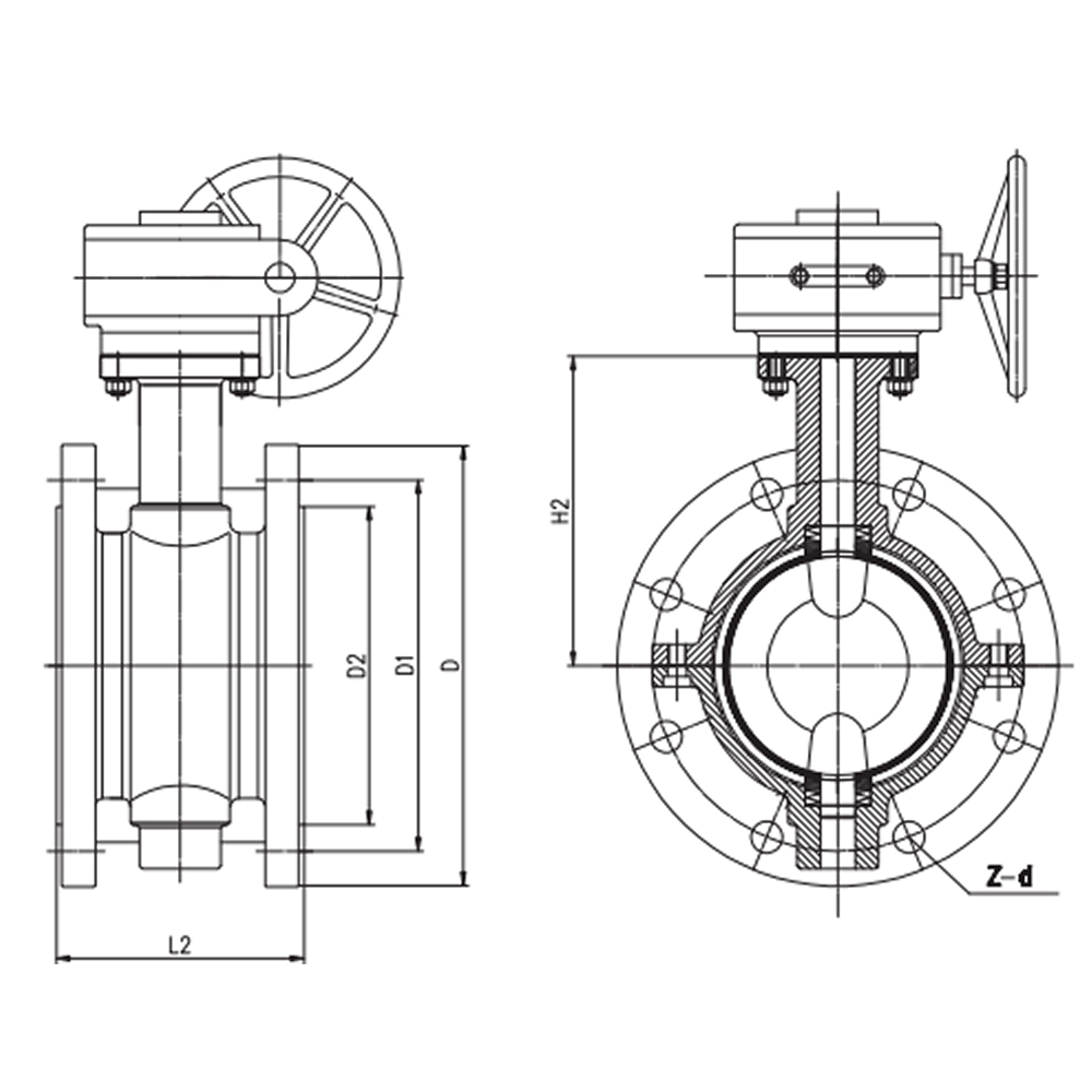
Main Shape Size and Connection Size (HG/T 20592 Unit: mm)
| DN | NPS | L1 (Wafer) | L2 (Flanged) | PN1.0MPa | PN1.6MPa | D2 | H1 | H2 | A | ||||
|---|---|---|---|---|---|---|---|---|---|---|---|---|---|
| D | D1 | Z-d | D | D1 | Z-d | ||||||||
| 40 | 1 1/2 | 40 | 106 | 150 | 110 | 4-18 | 150 | 110 | 4-18 | 70 | 60 | 90 | 78 |
| 50 | 2 | 43 | 108 | 165 | 125 | 4-18 | 165 | 125 | 4-18 | 90 | 70 | 112 | 96 |
| 65 | 2 1/2 | 46 | 112 | 185 | 145 | 4-18 | 185 | 145 | 4-18 | 110 | 80 | 125 | 112 |
| 80 | 3 | 46 | 114 | 200 | 160 | 8-18 | 200 | 160 | 8-18 | 130 | 89 | 135 | 130 |
| 100 | 4 | 52 | 127 | 220 | 180 | 8-18 | 220 | 180 | 8-18 | 148 | 105.5 | 142 | 150 |
| 125 | 5 | 56 | 140 | 250 | 210 | 8-18 | 250 | 210 | 8-18 | 181 | 121 | 165 | 178 |
| 150 | 6 | 56 | 140 | 285 | 240 | 8-22 | 285 | 240 | 8-22 | 202 | 145 | 180 | 206 |
| 200 | 8 | 60 | 152 | 340 | 295 | 8-22 | 340 | 295 | 12-22 | 263 | 177 | 228 | 260 |
| 250 | 10 | 68 | 165 | 395 | 350 | 12-22 | 405 | 355 | 12-26 | 313 | 205 | 278 | 317 |
| 300 | 12 | 78 | 178 | 445 | 400 | 12-22 | 460 | 410 | 12-26 | 368 | 235 | 295 | 367 |
| 350 | 14 | 78 | 190 | 505 | 460 | 16-22 | 520 | 470 | 16-26 | 415 | 260 | 341 | 466 |
| 400 | 16 | 102 | 216 | 565 | 515 | 16-26 | 580 | 525 | 16-30 | 484 | 299 | 390 | 495 |
| 450 | 18 | 114 | 222 | 615 | 565 | 20-26 | 640 | 585 | 20-30 | 519 | 320 | 442 | 630 |
| 500 | 20 | 127 | 229 | 670 | 620 | 20-26 | 715 | 650 | 20-33 | 569 | 352.5 | 470 | 694 |
Technical Drawings
Core Features & Advantages
1. Full Lining, Zero Bare Metal in the Flow Path Body, disc, and seat contact zone — every surface the media touches is PTFE/PFA/FEP. No exposed metal, no galvanic corrosion, no pitting from stray acid contact. For applications where even a pinhole means a shutdown.
2. Split-Body with Encapsulated Stem Seal Two-piece bolted body clamps the liner in compression. The stem seal uses a fluororubber O-ring fully encapsulated in PFA — the elastomer never sees the media. Thermal cycles, aggressive solvents, oxidizing acids — the sealing element stays chemically isolated.
3. Five Lining Chemistries, 200°C Cap PTFE (–30~180°C), PFA (–30~200°C), FEP (–30~150°C), RPTFE, GXPO — one valve body, five chemical compatibility profiles. Match the lining to the process fluid, not the other way around.
4. DN50–DN1600, Three Connection Types Wafer fits between flanges at minimum face-to-face. Lug bolts into the line with downstream serviceability. Flanged RF drops into standard pipe specs. One lining platform, three installation geometries — no gap from small-bore to main-header.
5. HG/T 3704 + API 608, Dual Standard Chinese domestic and international project specifications on one valve. Shell tested to 1.5 MPa, low-pressure air seal at 0.6 MPa. No requalification when the project scope crosses borders.
Applications
- Strong acid transfer — hydrochloric, sulfuric, nitric, hydrofluoric
- Chlor-alkali process lines — caustic soda, wet chlorine
- Pharmaceutical intermediate and API synthesis
- Electroplating bath supply and effluent
- Steel pickling line acid circulation
- Organic solvent and mixed chemical distribution
- Flue gas desulfurization slurry and quench water
- Semiconductor wet-etch chemical delivery
Why Choose Fluorine lined butterfly valve?
1. The Liner Is the Valve Every surface in the flow path — body bore, disc face, seat ring, stem — wears PTFE, PFA, or FEP. No metal exposed. No corrosion allowance to calculate. No coating to inspect. The polymer is the pressure boundary’s chemical interface from flange to flange.
2. Stem Seal That Never Sees the Media The stem O-ring is fully encapsulated in PFA. The fluororubber inside does the sealing; the PFA jacket keeps the acid out. Thermal cycling, solvent attack, oxidizing fluids — the elastomer stays chemically blind to whatever is in the line.
3. Wafer, Lug, or Flanged — Same Lining DN50 wafer drops between flanges at 46 mm face-to-face. DN1600 flanged bolts into the main header. Lugged body lets you dead-end service and pull the downstream pipe without draining the line. One lining system, three installation geometries.
4 -30°C to 200°C Without a Material Change Order PFA lining on the same CF8/CF8M body handles cold caustic at –30°C and hot acid at 200°C. No dual inventory for seasonal swings, no alternate BOM for different process steps — one part number covers the full thermal and chemical envelope.
Full lining is not an upsell — it’s the answer when a pinhole costs more than the valve.


