


Fluorine lined regulator valve
Haoguang’s fluorine lined regulator valve modulates corrosive media with a single-seat piston plug, PTFE/PFA-lined body and bonnet — metal handles stress, fluoropolymer handles acid. ZJHA/B pneumatic actuator standard, electric optional. 50:1 turndown, equal-percentage or linear, leakage under 10⁻⁵ × rated Cv. DN20 to DN200. Precise control without expensive alloys.
- Nominal Diameter: DN20 – DN200
- Seat Diameter: 20 – 175 mm
- Rated Cv: 5 – 460
- Pressure Rating:PN1.0 · PN1.6 MPa
- Operating Temperature: –30 ~ 180°C
- Flow Characteristic & Rangeability: Linear / Equal-percentage · 50:1
- Leakage:≤ 10⁻⁵ × rated Cv
- Actuator:ZJHA/B pneumatic diaphragm (electric optional)
Technical Specifications
Material Specification
| DN | DN20-200 1″~8″ | |||
|---|---|---|---|---|
| Pressure | 1.0MPa 1.6MPa 150LB | |||
| NO. | Component Name | Material Details | ||
| 1 | Round Nut | A194 2H | A194 8 | A194 8M |
| 2 | Nut | A194 2H | A194 8 | A194 8M |
| 3 | Stud Bolt | A193 B7 | A320 B8 | A193 B8M |
| 4 | Gland Plate | SS304 | ||
| 5 | Packing | PTFE | ||
| 6 | Nut | A93 2H | A194 8 | A194 8M |
| 7 | Double-end Stud | A194 B7 | A320 B8 | A320 B8M |
| 8 | Bonnet | A216 WCB+Lining | A351 CF8 CF8M+Lining | A351 CF3 CF3M+Lining |
| 9 | Positioning Sleeve | SS304 | ||
| 10 | Stem | SS304 / SS316 | ||
| 11 | Gasket | SS304 | ||
| 12 | Bellows | PTFE | ||
| 13 | Plug | SS304+Lining Material / SS316+Lining Material | ||
| 14 | Pipe Joint | A216 WCB+Lining | A351 CF8 CF8M+Lining | A351 CF3 CF3M+Lining |
| 15 | Nut | A93 2H | A194 8 | A194 8M |
| 16 | Stud Bolt | A194 B7 | A320 B8 | A193 B8M |
| 17 | Body | A216 WCB+Lining | A351 CF8 CF8M+Lining | A351 CF3 CF3M+Lining |
Main Parameters of Pneumatic Lined Control Valve
| Nominal Diameter DN | 20 | 32 | 40 | 50 | 65 | 80 | 100 | 125 | 150 | 200 | |||||||||
|---|---|---|---|---|---|---|---|---|---|---|---|---|---|---|---|---|---|---|---|
| Seat Diameter (mm) | 20 | 25 | 25 | 32 | 32 | 40 | 40 | 50 | 50 | 65 | 65 | 80 | 80 | 100 | 100 | 110 | 125 | 150 | 175 |
| Rated Cv Value | 5 | 10 | 10 | 16 | 16 | 24 | 24 | 44 | 44 | 68 | 68 | 125 | 125 | 165 | 165 | 195 | 330 | 360 | 460 |
| Rated Stroke (mm) | 16 | 25 | 38 | 50 | 60 | ||||||||||||||
| Actual Pressure | Max 1.0MPa (1.6MPa Custom) | ||||||||||||||||||
| Nominal Pressure | PN1.0, 1.6MPa | ||||||||||||||||||
| Working Temp. | -30°C ~ +180°C | ||||||||||||||||||
| Plug Type | Single-seat plunger plug | ||||||||||||||||||
| Flow Characteristic | Linear, Equal percentage | ||||||||||||||||||
| Adjustable Range | 50:1 | ||||||||||||||||||
| Equipped with ZJHA/B Multi-spring Diaphragm Actuator | |||||||||||||||||||
| Model | ZJHA/B-22 | ZJHA/B-23 | ZJHA/B-34 | ZJHA/B-45 | |||||||||||||||
| Action Type | ZJHA model realizes “Air to Close” action; ZJHB model realizes “Air to Open” action | ||||||||||||||||||
| Air Supply Pressure | Spring range: 0.02~0.10, 0.04~0.20, 0.08~0.24MPa, respectively 0.14, 0.25, 0.35MPa | ||||||||||||||||||
| Air Connection | Rc1/4 | ||||||||||||||||||
| Basic Error | Without positioner ±5%; With positioner ±1% | ||||||||||||||||||
| Hysteresis | Without positioner ±5%; With positioner ±1% | ||||||||||||||||||
| Dead Zone | Without positioner ±3%; With positioner ±0.4% | ||||||||||||||||||
| End Point Error | Without positioner: Starting point ±2.5%, End point ±5%; With positioner: Starting & End point error ±1% | ||||||||||||||||||
| Stroke Deviation | ±2.5% | ||||||||||||||||||
| Leakage | Not exceeding 10-5 of rated Cv value | ||||||||||||||||||
| Optional Accessories | Positioner, Air filter regulator, Solenoid valve, Limit switch, etc. (Provided as per order requirements) | ||||||||||||||||||
Actuator Models and Basic Parameters
Allowable Pressure Difference of Pneumatic Multi-spring Diaphragm Actuator
| Action Type | Actuator | Diaphragm Area cm² | Air Supply Pressure MPa | Spring Range MPa | Allowable Pressure Difference 100KPa | |||||||||||
|---|---|---|---|---|---|---|---|---|---|---|---|---|---|---|---|---|
| 20 | 25 | 32 | 40 | 50 | 65 | 80 | 100 | 110 | 125 | 150 | 175 | |||||
| Air to Close | ZJHA-22/23 | 350 | 0.14 | 0.02~0.10 | 12 | 7.6 | 6.3 | 4.0 | 2.6 | – | – | – | – | – | – | – |
| 0.28 | 0.04~0.20 | 16 | 16 | 14 | 12 | 7.6 | – | – | – | – | – | – | – | |||
| 0.35 | 0.08~0.24 | 16 | 16 | 16 | 16 | 12 | – | – | – | – | – | – | – | |||
| ZJHA-34 | 560 | 0.14 | 0.02~0.10 | 16 | 10 | 7.5 | 6.6 | 4.2 | 2.4 | 1.6 | 1.0 | – | – | – | – | |
| 0.28 | 0.04~0.20 | – | – | 16 | 12 | 9.8 | 5.6 | 3.8 | 2.9 | – | – | – | – | |||
| 0.35 | 0.08~0.24 | – | – | 16 | 16 | 16 | 13 | 8.6 | 5.5 | – | – | – | – | |||
| ZJHA-45 | 900 | 0.14 | 0.02~0.10 | – | – | – | – | – | 5.4 | 3.6 | 2.3 | 1.7 | 1.1 | 0.7 | 0.2 | |
| 0.28 | 0.04~0.20 | – | – | – | – | – | 9.3 | 6.1 | 3.9 | 2.5 | 1.7 | 1.1 | 0.7 | |||
| 0.35 | 0.08~0.24 | – | – | – | – | – | 14 | 9.8 | 8.2 | 5.2 | 3.7 | 2.5 | 1.6 | |||
| ZJHA-56 | 1500 | 0.14 | 0.02~0.10 | – | – | – | – | – | – | 5.6 | 4.0 | 2.6 | 1.7 | 1.1 | 0.7 | |
| 0.28 | 0.04~0.20 | – | – | – | – | – | – | – | – | 9.1 | 5.8 | 3.5 | 2.5 | |||
| 0.35 | 0.08~0.24 | – | – | – | – | – | – | – | – | 11 | 8.8 | 5.7 | 3.5 | |||
| Air to Open | ZJHB-22/23 | 350 | 0.14 | 0.02~0.10 | 10 | 7.6 | 4.6 | 2.6 | 1.3 | – | – | – | – | – | – | – |
| 0.28 | 0.04~0.20 | 16 | 16 | 11 | 9.6 | 6.1 | – | – | – | – | – | – | – | |||
| 0.35 | 0.08~0.24 | 16 | 16 | 16 | 16 | 10 | – | – | – | – | – | – | – | |||
| ZJHB-34 | 560 | 0.14 | 0.02~0.10 | – | 12 | 6.1 | 4.2 | 2.4 | 1.2 | 0.6 | 0.4 | – | – | – | – | |
| 0.28 | 0.04~0.20 | – | – | 16 | 12 | 8.2 | 5.6 | 3.8 | 2.4 | – | – | – | – | |||
| 0.35 | 0.08~0.24 | – | – | 16 | 16 | 16 | 7.2 | 4.8 | 3.5 | – | – | – | – | |||
| ZJHB-45 | 900 | 0.14 | 0.02~0.10 | – | – | – | – | – | 9.8 | 1.6 | 1.1 | 0.7 | 0.4 | 0.2 | 0.1 | |
| 0.28 | 0.04~0.20 | – | – | – | – | – | – | 4.8 | 3.2 | 1.7 | 0.8 | 0.4 | 0.2 | |||
| 0.35 | 0.08~0.24 | – | – | – | – | – | – | 8.2 | 5.2 | 3.7 | 2.5 | 1.7 | 0.7 | |||
| ZJHB-56 | 1500 | 0.14 | 0.02~0.10 | – | – | – | – | – | – | 4.0 | 2.6 | 1.7 | 1.1 | 0.7 | 0.2 | |
| 0.28 | 0.04~0.20 | – | – | – | – | – | – | – | – | 3.9 | 2.5 | 1.7 | 0.7 | |||
| 0.35 | 0.08~0.24 | – | – | – | – | – | – | – | – | 8.4 | 5.4 | 3.7 | 1.6 | |||
Allowable Pressure Difference of Electric Actuator
| Actuator Thrust N.m | Allowable Pressure Difference 100KPa | |||||||||||
|---|---|---|---|---|---|---|---|---|---|---|---|---|
| 20 | 25 | 32 | 40 | 50 | 65 | 80 | 100 | 110 | 125 | 150 | 175 | |
| 800 | 16 | 16 | 6.9 | 4.5 | – | – | – | – | – | – | – | – |
| 1000 | – | 16 | 8.7 | 5.5 | 3.5 | – | – | – | – | – | – | – |
| 2000 | – | – | 16 | 11 | 7.1 | 4.2 | – | – | – | – | – | – |
| 3000 | – | – | – | 16 | 11 | 6.3 | 4.1 | – | – | – | – | – |
| 6500 | – | – | – | – | – | 13.7 | 9.0 | 5.7 | – | – | – | – |
| 9000 | – | – | – | – | – | – | 12.5 | 8.0 | 5.1 | – | – | – |
| 12000 | – | – | – | – | – | – | – | 11 | 6.8 | 4.7 | – | – |
| 16000 | – | – | – | – | – | – | – | – | 9.1 | 6.3 | 4.7 | 3.6 |
Note: The recommended allowable pressure differences above are relative. We offer multiple configuration combinations for various pressure differences. For complex control systems, please contact our technical department. With our years of experience in producing process control products, we will provide you with a more optimized actuator configuration.
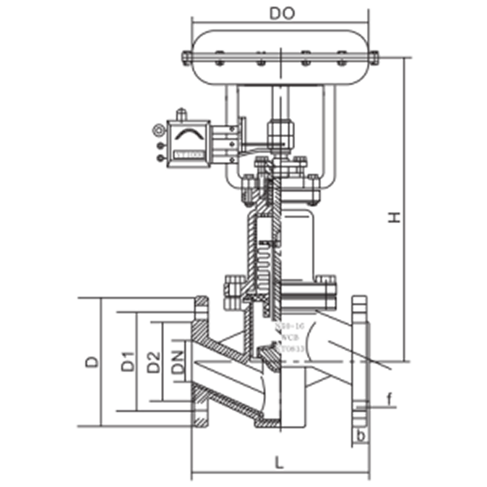
HG/T 20592 PN16 Dimensions (Unit: mm)
| DN | L | D | D1 | D2 | b | f | n-d | Thread | H | A |
|---|---|---|---|---|---|---|---|---|---|---|
| 20 | 160 | 105 | 75 | 56 | 15 | 2.5 | 4-14 | – | 440 | 285 |
| 25 | 160 | 115 | 85 | 65 | 16 | 3 | 4-14 | – | 440 | 285 |
| 32 | 180 | 135 | 100 | 78 | 16 | 3 | 4-18 | – | 466 | 285 |
| 40 | 200 | 150 | 110 | 85 | 16 | 3 | 4-18 | – | 495 | 285 |
| 50 | 230 | 165 | 125 | 100 | 16 | 3 | 4-18 | – | 495 | 285 |
| 65 | 290 | 180 | 145 | 120 | 18 | 3.5 | 4-18 | – | 615 | 360 |
| 80 | 310 | 200 | 160 | 135 | 20 | 3.5 | 8-18 | 2-M16 | 605 | 360 |
| 100 | 350 | 220 | 180 | 155 | 21 | 3.5 | 8-18 | 2-M16 | 630 | 360 |
| 125 | 400 | 250 | 210 | 185 | 23 | 4 | 8-18 | 2-M16 | 760 | 470 |
| 150 | 480 | 285 | 240 | 210 | 24 | 4 | 8-22 | 2-M20 | 775 | 470 |
| 200 | 600 | 340 | 295 | 265 | 26 | 4.5 | 12-22 | 2-M20 | 835 | 470 |
Technical Drawings
Core Features & Advantages
1. Single-Seat Piston Plug — One Seat, One Leak Path Unlike double-seat designs that balance forces at the cost of two leak paths, the single-seat piston plug has exactly one sealing surface. Leakage at or below 10⁻⁵ × rated Cv — that’s Class VI shutoff territory for an acid-grade modulating valve.
2. PTFE/PFA Lined Body and Bonnet — Metal Stays Dry The entire wetted flow path is fluoropolymer. The cast steel body bears pressure, the plug moves inside a lined seat ring, and the bonnet keeps packing away from the process. Zero corrosion allowance needed on the pressure boundary.
3. ZJHA/B Diaphragm Actuator — Tuned Spring, Tuned Response Multi-spring diaphragm design gives consistent thrust across the stroke. ZJHA = air-to-close (fail-open), ZJHB = air-to-open (fail-close). Supply pressure from 0.14 to 0.35 MPa covers the full range of seat diameters from 20 to 175 mm. Spring range selected to match your actual ΔP.
4. 50:1 Turndown — Linear or Equal-Percentage, Your Choice Linear for level control, equal-percentage for pressure and flow loops. Same plug-to-seat geometry handles both with a profile change. 50:1 rangeability means you can throttle at 2% of full flow and still get stable control — no hunting, no overshoot.
5. Electric-Ready — Same Valve, Two Actuators The valve body doesn’t care whether a pneumatic diaphragm or an electric actuator sits on top. 800 to 16,000 N·m electric thrust options map to the same mounting flange. For remote stations without instrument air, swap the actuator and keep the same spare parts.
Applications
- Acid concentration and dilution control loops
- Reactor temperature regulation via heating/cooling jacket flow
- pH adjustment — acid dosing to neutralization tanks
- Chlor-alkali process — brine flow, chlorine gas pressure control
- Hydrofluoric acid alkylation unit flow and level loops
- Mixed-acid etching bath make-up and bleed control
- Liquid chlorine vaporizer pressure regulation
- Pharma and fine-chemical batch reactor feed modulation
- Fume scrubber make-up water and chemical dosing
Why Choose Fluorine lined regulator valve?
1. Class VI shutoff on an acid-grade modulating valve Leakage ≤ 10⁻⁵ × rated Cv — that’s tight-shutoff territory, not typical regulating-valve leakage. Single-seat piston plug, one sealing surface, no second leak path to compromise the spec. Close it and it stays closed.
2. Lined body, not exotic alloys PTFE/PFA-lined WCB or CF8/CF8M costs a fraction of Hastelloy or titanium. Same corrosion resistance where it matters — the wetted path. The metal body is structural, the lining is chemical. Budget stays reasonable, process stays safe.
3. 50:1 turndown with real stability Linear for level, equal-percentage for flow and pressure. Same plug geometry covers both with a profile change. Control at 2% of full flow without hunting — rare in a lined valve where friction and stiction usually kill low-end response.
4. One valve, pneumatic or electric — same spare parts The body and trim don’t change whether a ZJHA/B diaphragm or an electric actuator sits on top. Remote station without instrument air? Swap the actuator, keep the same plug, seat, and packing on the shelf.
Haoguang Fluorine Lined Regulator Valves — modulate the acid, not the alloy. DN20 to DN200, pneumatic or electric, linear or equal-percentage. Precise control costs less than you think.


